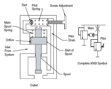
Hydraulic Pilot Operated Relief Valve
The direct acting and pilot operated relief valve have a different pressure vs. flow curve although both of them perform the same function. The pilot operated relief valve allows the operation over a wider pressure range.
The figure above shows the functional diagram of pilot-operated relief valve. The orifice on the main spool balanced the pressure on the top and bottom of the skirt.
The pilot section of the valve located at the top section. A dart is held in place by the pilot spring. When the hydraulic force on this dart becomes greater than the pilot spring force, the dart is unseated, and fluid flows from the cavity above the skirt, through an internal drain to the valve outlet. Flow through the orifice replaces the fluid lost from the cavity above the skirt. The spool is still held in position by the main spool spring.
The pilot operated relief valve allow a low cracking pressure as low as 100 psi while the direct acting relief valve need 1500 psi to crack.
A pilot-operated relief valve can be used with a remote pilot. The remote pilot has the same functions like the built pilot and it allows the setting of two pressure levels on one main relief valve.
Categories: Pressure Control Valves | Tags: pilot, Relief Valve | Leave a comment

